

NDE for Pipe Joints

1. Introduction
Non-Destructive Examination (NDE) plays a crucial role in ensuring the integrity of welded pipe joints. The selection of NDE methods depends on material type, pipe thickness, and applicable American codes such as ASME B31.3, ASME Section V, and API 1104.
This blog discusses appropriate NDE techniques for carbon steel, stainless steel, duplex stainless steel, super duplex stainless steel, and alloy steel, considering wall thickness criteria.
2. Overview of NDE Methods
2.1 Radiographic Testing (RT)
• Detects internal defects like porosity, slag inclusions, and lack of fusion.
• Film-based (Conventional RT) or Digital (Computed/Digital RT).
• Restricted in high-density materials and thick sections.
2.2 Ultrasonic Testing (UT)
• Uses sound waves to detect volumetric flaws and weld discontinuities.
• Conventional UT is effective for thicker pipes.
• Phased Array UT (PAUT) provides a more detailed assessment.
• Time of Flight Diffraction (TOFD) is used for high-precision flaw sizing.
2.3 Magnetic Particle Testing (MT)
• Detects surface and near-surface cracks in ferromagnetic materials.
• Not applicable to stainless steels (non-magnetic grades).
2.4 Liquid Penetrant Testing (PT)
• Detects surface-breaking flaws.
• Suitable for all materials, including stainless steel, duplex, and super duplex.
2.5 Visual Testing (VT)
• A primary inspection method is required by all codes.
• Used to identify surface defects before and after welding.

3. NDE Methods Based on Material and Wall Thickness
3.1 Carbon Steel
• Thin-wall pipes (<6 mm / 0.24”):
• RT (Preferred for detecting internal defects).
• UT (Alternative if RT is restricted).
• VT, PT/MT (Surface inspection).
• Thick-wall pipes (>6 mm / 0.24”):
• UT / PAUT (Preferred for deep penetration).
• RT (For confirming volumetric defects).
• MT (For surface defect detection).
📌 Code References: ASME B31.3, ASME Section V, API 1104.
3.2 Stainless Steel (Austenitic & Ferritic Grades)
• Thin-wall pipes (<6 mm / 0.24”):
• RT (Primary method).
• PT (Surface flaws).
• Thick-wall pipes (>6 mm / 0.24”):
• UT / PAUT (Preferred over RT due to better penetration).
• PT (For surface discontinuities).
📌 Code References: ASME Section V, ASME B31.3, AWS D1.6.
3.3 Duplex & Super Duplex Stainless Steel
• Thin-wall pipes (<6 mm / 0.24”):
• RT (Preferred for volumetric defects).
• PT (Surface defects).
• Thick-wall pipes (>6 mm / 0.24”):
• PAUT / TOFD (Preferred over RT due to grain structure affecting X-ray penetration).
• PT (For detecting surface cracks).
📌 Code References: ASME Section V, ASME B31.3.
3.4 Alloy Steel (Chromium-Molybdenum, Nickel-Based Alloys, etc.)
• Thin-wall pipes (<6 mm / 0.24”):
• RT (For internal defects).
• PT (For surface flaws).
• Thick-wall pipes (>6 mm / 0.24”):
• PAUT / TOFD (Preferred over RT due to improved detection in heavy-wall sections).
• PT (For surface inspection).
📌 Code References: ASME Section V, ASME B31.3, API 1104.
4. Summary Table: NDE Selection Based on Material and Wall Thickness
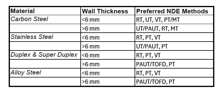
NDE Summary Table
NDE Table as per wall thickness and material.
5. Conclusion
Choosing the correct NDE method depends on material properties, wall thickness, and code requirements. While RT is widely used, advanced methods like PAUT and TOFD are preferred for thick-walled and complex materials. Surface inspections (MT/PT) are always essential for detecting external defects.
For compliance, always refer to ASME B31.3, ASME Section V, and API 1104 when specifying NDE procedures.
Here is the detailed description of NDE Methods:
1. Radiographic Testing (RT)
📌 Purpose: Detects internal defects like porosity, slag inclusions, lack of fusion, and incomplete penetration.
Types of RT:
1. Conventional Film Radiography (RT-F)
• Uses X-ray or gamma rays to create an image on film.
• The film is processed chemically to reveal defects.
• Provides high-resolution images but requires long exposure times.
2. Computed Radiography (CR)
• Uses a digital phosphor imaging plate instead of traditional film.
• Faster processing compared to film-based RT.
3. Digital Radiography (DR)
• Uses flat-panel detectors (FPD) for real-time digital imaging.
• Faster, but expensive.
✅ Advantages:
✔️ Can detect internal defects in any material.
✔️ Well-established and widely accepted.
❌ Limitations:
❌ Not effective for thick-walled or high-density materials (e.g., duplex stainless steel).
❌ Radiation safety concerns require special handling.
📜 Codes & Standards: ASME Section V, ASME B31.3, API 1104.
2. Ultrasonic Testing (UT)
📌 Purpose: Uses high-frequency sound waves to detect internal defects like cracks, lack of fusion, and porosity.
Types of UT:
1. Conventional UT (Manual UT or Straight Beam UT)
• A single ultrasonic probe transmits and receives sound waves.
• Used for thicker welds and detects volumetric flaws.
2. Angle Beam UT (Shear Wave UT)
• Uses an angled transducer to scan weld joints.
• Common in butt weld inspections in piping.
✅ Advantages:
✔️ No radiation hazards.
✔️ Deeper penetration than RT for thick materials.
❌ Limitations:
❌ Requires skilled interpretation.
❌ Difficult for coarse-grained materials like duplex stainless steel.
📜 Codes & Standards: ASME Section V, AWS D1.1, API 1104.
3. Phased Array Ultrasonic Testing (PAUT)
📌 Purpose: Advanced version of UT that uses multiple ultrasonic beams to scan welds at different angles.
How It Works:
• Uses an array of ultrasonic elements that can be electronically controlled.
• Creates high-resolution images of the weld.
• Real-time visualization for better defect detection.
✅ Advantages:
✔️ Provides detailed imaging of defects.
✔️ Faster and more reliable than conventional UT.
✔️ Used for thicker pipes and critical welds.
❌ Limitations:
❌ More expensive than conventional UT.
❌ Requires specialized training.
📜 Codes & Standards: ASME Section V, API 1104.
4. Time of Flight Diffraction (TOFD)
📌 Purpose: Uses ultrasonic waves to measure defect depth and size with high accuracy.
How It Works:
• Uses two probes placed on opposite sides of the weld.
• Diffraction signals from defect edges are analyzed to determine flaw size.
✅ Advantages:
✔️ Very accurate for crack detection.
✔️ Faster than conventional UT.
✔️ Ideal for thick-wall pipes.
❌ Limitations:
❌ Less effective for small defects.
❌ Requires specialized equipment and expertise.
📜 Codes & Standards: ASME Section V, API 1104.
5. Magnetic Particle Testing (MT)
📌 Purpose: Detects surface and near-surface cracks in ferromagnetic materials (e.g., carbon steel).
How It Works:
• The weld is magnetized using a magnetic yoke or coil.
• Iron particles are applied; they accumulate around cracks.
• Cracks appear visibly under white or UV light.
✅ Advantages:
✔️ Simple and fast inspection.
✔️ Detects fine surface cracks.
❌ Limitations:
❌ Only works on ferromagnetic materials (Not for stainless steel or duplex).
❌ Cannot detect deep internal defects.
📜 Codes & Standards: ASME Section V, API 1104.
6. Liquid Penetrant Testing (PT)
📌 Purpose: Detects surface-breaking cracks in any material.
How It Works:
1. Penetrant dye is applied to the weld.
2. After a short dwell time, the excess dye is removed.
3. Developer powder is applied to draw out trapped dye from cracks.
4. Cracks become visible under normal or UV light.
✅ Advantages:
✔️ Works on all materials, including stainless steel and duplex.
✔️ Simple and inexpensive method.
❌ Limitations:
❌ Only detects surface cracks (not internal defects).
❌ Requires clean, dry surfaces.
📜 Codes & Standards: ASME Section V, API 1104.
7. Visual Testing (VT)
📌 Purpose: The first step in NDE, used to detect weld discontinuities, undercuts, cracks, and porosity.
How It Works:
• Conducted before, during, and after welding.
• Uses tools like magnifiers, borescopes, and weld gauges.
✅ Advantages:
✔️ Quick and inexpensive.
✔️ Helps detect visible welding defects early.
❌ Limitations:
❌ Cannot detect internal defects.
📜 Codes & Standards: ASME B31.3, API 1104.

Conclusion
Selecting the right NDE method depends on material type, pipe thickness, and defect type. RT and UT are widely used for internal defects, while MT and PT are effective for surface flaws. PAUT and TOFD provide advanced imaging for thick-walled materials.