

Blind Flange Thickness Calculation
Here you can find the calculation of the minimum blind flange wall thickness based on internal design pressure and design temperature for bolted and circular blind flange, per ASME B31.3 and ASME Section VIII, Division 1, UG-34.
To find the thickness of the blind flange we need to find the bolt load as well. At the end, we will have an example calculation for you to see how to find the blind flange thickness.

Nomenclature:
c = sum of mechanical allowances (thread or groove depth) plus corrosion and erosion allowances, in
P = internal and external design gage pressure, psig
S = maximum allowable stress value in tension at the design temperature, psi
t =pressure design thickness, as calculated for the given styles of blind flange, using the appropriate equations for bolted flat cover plates in UG-34, in
C = a factor depending upon the attachment method of the head, shell dimensions, and other items as listed in Section VIII-div.1-UG-34- d.
0.3 is to be used acc. to Fig. UG-34
d = diameter, or short span, measured as indicated in Fig. UG-34, in
E =joint efficiency factor. 1 is to be used due to seamless material
hg=gasket moment arm, equal to the radial distance from the center line of the bolts to the line of the gasket reaction, as shown in Table 2-5.2 (refer to Append 2), in
W= total bolt load, lb, for operating conditions W = Wm1
G=diameter, in., at the location of the gasket load reaction
b=effective gasket or joint-contact-surface seating width, in, as shown Table 2-5.2 (refer to Man. Appendix 2)
m=gasket factor, obtained from Table 2-5.1 (refer to Man. Appendix 2)
Am=total required cross‐sectional area of bolts (Refer to Man. Appendic-2, 2.3)
Ab=cross‐sectional area of the bolts using the root diameter of the thread or least diameter of unthreaded position, if less
(Refer to Man. Appendic-2, 2.3)

Effective Gasket Width
Table 2-5.2 of ASME Section VIII Div. 1 Man. Appendix-2
The minimum wall thickness of blind flanges shall be determined per the following equation:
(1) tm=t+c
Considering the manufacturer’s minus tolerance, the minimum wall thickness shall be not less than tm.
To calculate t, the rules of ASME Section VIII, Division1, UG-34, which is referred from ASME B31.3.
(2) t = d√(CP/SE+1.9Whg /SEd^3 )
When using formula (2), the thickness t shall be calculated for both operating conditions and gasket seating, and the greater of the two values shall be used.
For operating conditions, the value of P shall be the design pressure, and the value of S at the design temperature and W = Wm1 shall be used.
For gasket seating, P equals zero, and the values of S at atmospheric temperature and W = ((Am+Ab)*Sa)/2.
Since the value of t for operating conditions is greater than the gasket seating, W is considered equal to Wm1.
Required Bolt Load Calculation According to ASME Section VIII-Division 1 Appendix-2
The required bolt load for the operating conditions Wm1 shall be sufficient to resist the hydrostatic end force H exerted by the maximum allowable working pressure on the area bounded by the diameter of the gasket reaction, and in addition, to maintain on the gasket or joint- contact surface a compression Hp, which experience has shown to be sufficient to assure a tight joint.
The required bolt load for the operating conditions Wm1 is determined in accordance with formula (3)
(3) Wm=H+Hp = 0,785G^2 P+(2b x 3,14GmP)

Pipe Stress Engineering by PENG
Let’s Look at an example:
In our example the size of the pipe is 10” (DN 250) and the Blind Flange Material is ASTM A 105. The material of the gasket is mineral fibre and the pressure rating is PN 10 or ASTM Class 150.
Before we should calculate the bolt load (W) and then we can put the figures in the formula of thickness calculation.
You can find the calculation table below.
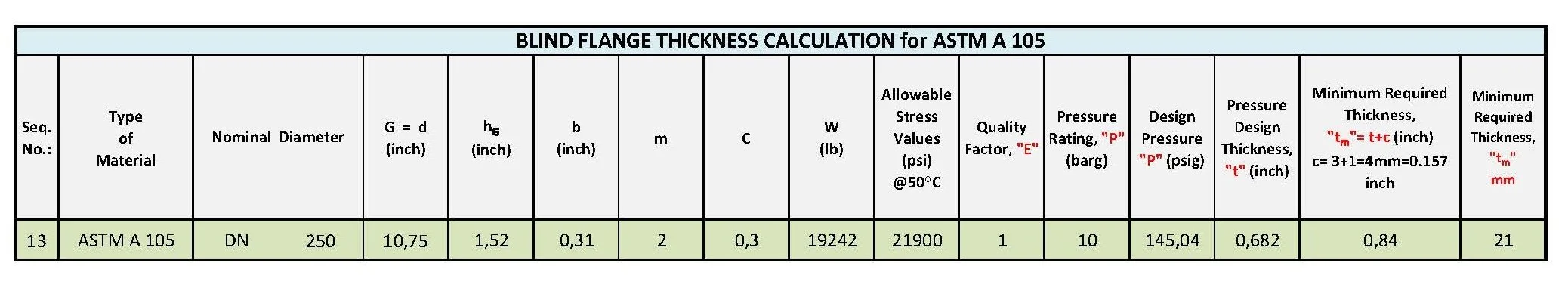
BLIND FLANGE CALCULATION TABLE (ASTM A 105)

This book is designed to give you a reference to the torque procedure and sequence of torque patterns for bolts and fasteners on flanges, vessels, reactors, fin fans, exchangers, etc. these torque patterns are generally used in installations of piping systems in refineries, gas plants, chemical plants, power plants, compressor stations, etc.


Reciprocating compressor piping systems are highly sensitive to pulsation and vibration effects caused by dynamic pressure fluctuations. If these effects are not properly considered during the design stage, they may lead to excessive vibration, fatigue damage at branch connections, and even premature failure of piping components. For this reason, an analogical (acoustic and pulsation) study plays a critical role in evaluating the dynamic behavior of compressor piping systems.