

Flange Bolting Preload Calculation
Flanges are the main critical elements of the industrial piping.They are used for connecting pipes to equipments, valves and etc. Flanges are the main resources of leakages. When you go through the internet / literature you may see lots of flange prooblems due to the lack of engineering and workmanship in construction.
The main causes of flange leakage are:
Uneven Bolt Stress
Improper Flange Alignment
Improper Gasket Centering
Dirty or Damaged Flange Faces
Excessive Piping System Loads at Flange Locations
Thermal Shock
High Vibration Levels
This article aims to focus on calculating the flange preload forces and creating torque tables for critical/ non-critical flanges." With the guidance of this specification and tables, the site construction team will prepare their own method of statements, procure their lubricants, and select their torque equipment.
The torque tables are built on specific assumptions regarding bolt and nut factors. These assumptions should be verified before using a given torque table to ensure they are appropriate for the specific application.
Even if all assumptions are appropriate, results may vary depending on conditions. Many factors induce scatter in the results or increase the inherent variability in the bolting process. These include variations in the nut factor, bolt, flange, and nut condition, equipment calibration and condition, and perpendicularity of the bolt, nut, and flange.
The values in the tables are based on the equation:
T = Torque value
F = Bolt pre-load
k = Nut Factor based on lubricant used
d = Nominal bolt diameter, (in.)
WHAT IS NUT FACTOR?
The nut factor is not the coefficient of friction.It is an experimentally derived constant that includes the impact of friction. The nut factor is strongly correlated with the lubricant used.It shall be mandatory (according to me!) to use lubricant in bolted connections in order to guarantee required torque on the bolt as preload. If the bolt is not cleaned and lubricant is not used, you may have some additional friction forces which may decrease the preload on the bolts.

As shown, a small portion of the applied torque (roughly 10 percent) actually results in useable bolt load available that ends up applied to the gasket; a majority of that torque is consumed by friction between the threads of the stud or bolt and nut or blind hole, and the flange surface under the head of the bolt or nut. That value of useable bolt force can be increased using a more effective lubricant with a lower K factor, which reduces the overall friction effect on the assembly.
HOW TO CALCULATE TORQUE?
Normally, in the design specifications, Piping Stress Engineers assume %50-%70 of the bolt's percent yield stress for determining the recommended preload force and calculating the total torque. You can follow this basic approach. Please see the link below for an online calculator.

Here Enter & Select
Flange Type
Flange Class
Flange Size
Bolt Type (Select Stud)
Fastener Material
Bolt Percent Yield (%50-%70)
K-Factor
The other values are calculated or filled automatically.
K FACTOR, WHICH VALUE SHALL BE TAKEN?
Since the K factor affects the torque value very closely, perform good research before choosing the correct value. Clearly indicate your assumptions in your calculated tables. I prefer to use K=0,16 for a well-lubricated bolted joint.
See the table below for the Nut Factor of some lubricants.


This book is designed to give you a reference to the torque procedure and sequence of torque patterns for bolts and fasteners on flanges, vessels, reactors, fin fans, exchangers, etc. these torque patterns are generally used in installations of piping systems in refineries, gas plants, chemical plants, power plants, compressor stations, etc.
TORQUE TABLES
You can find standardised Torque Tables in ASME PCC-1, . You can check your result and assumption with the tables prepared and tabulatedin PCC-1.
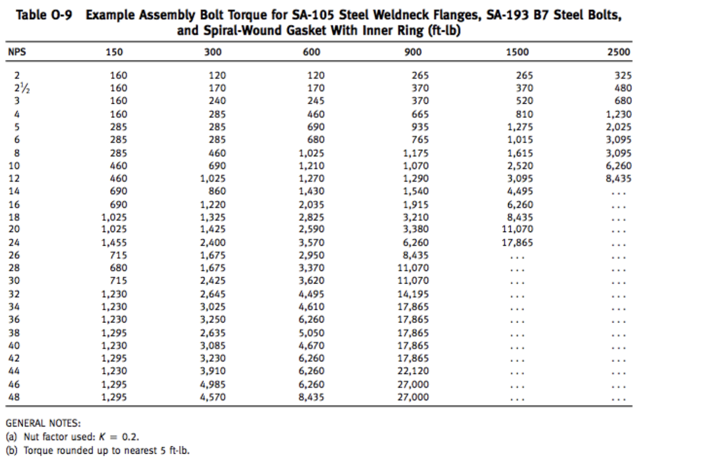
ASME PCC-1 Torque Table

The assumptions & notes for the table above are:
Bolting torque to develop 50% Bolt Yield Stress at Nut Factor, K=0.16
This Table applies to Never-Seize paste and Fel-Pro lubricant, K=0.16.
The above Table applies only to ASTM A320 Grade L7, A193 Grade B7, and A193 Grade B16 Stud Bolts.
The torque values are approved for spiral wound graphite and PTFE-filled gaskets, graphite sheet gaskets of GHE and GHR types, ring joint, double-jacketed, and Camprofile gaskets with graphite and PTFE lining.
The Final Torque Value accounts for 10% bolt relaxation.
This Table is not acceptable for PTFE coated Stud Bolts and nuts.
AUTHORS
Erhan Yıldız, BS Mechanical Engineer, Co-Founder - KEY OIL & GAS
Ozan Gülser, MS Mechanical Engineer, Co-Founder - KEY OIL & GAS
Halil Ünal, Piping & Plant Specialist, Co-Founder - KEY OIL & GAS
Reference:
1- https://www.wermac.org/bolts/bolts_bolting-torque-tables_stud-bolts_flange-bolt-up_table3.html
2- https://www.pumpsandsystems.com/importance-using-thread-lubricants-bolted-connections
3- Guideline for bolted joint design and analysis: version 1.0, Kevin H. Brown, Charles Morrow, Samuel Durbin, and Allen Baca
4- Guidelines for Pressure Boundary Bolted Flange Joint Assembly
5- http://www.wermac.org/flanges/flanges_bolting-torque-tables_table2.html