

Buried Pipeline Stress Analysis KEY Points
The governing codes for pipe stress analysis are generally ASME B31.3 and 31.1. However, the approach to Pipeline Stress Analysis is different from the aforementioned codes. In this blog, the main aspects and key points of pipeline stress analysis will be explained briefly.
ASME B31.4 covers piping systems transporting liquids, such as crude oil, condensate, natural gasoline, natural gas liquids, liquefied petroleum gas, liquid alcohol, liquid anhydrous ammonia, and liquid petroleum products, between producers’ lease facilities, such as tank farms, pump stations, natural gas processing plants, refineries, ammonia plants, terminals (marine, rail, and truck), and other delivery and receiving point.
A reasonable estimate of the movement and its interaction with the end resistance force afforded by connecting piping and equipment are very important aspects of designing a pipeline. The key points for stress analysis are as follows:
B 31.4 code addresses analysis of lines within temperature range starting from -20 degrees centigrade till 120 degrees centigrade.
There are no Sh values similar to B 31.3. A pipeline normally runs for several kilometers without any fittings attached. Because of such simplicity, the stress in most pipelines is quite predictable. Taking advantage of this characteristic, the code’s allowable stress for a pipeline is greatly increased compared to that for plant piping. All allowable values are linked with Sy (Specified Minimum Yield Strength), as the allowable stress of a pipeline is mainly to protect the pipe from gross deformation. Whenever you select B 31.4 in Caesar II, all Sh value fields will become grey.

Allowable Stress Section of Caesar II
All allowable values are linked with Sy (Specified Minimum Yield Strength), as the allowable stress of a pipeline is mainly to protect the pipe from gross deformation. Whenever you select B 31.4 in Caesar II, all Sh value fields will become grey.
The following equations are used to calculate various stress allowable:
* Expansion Allowable=(0.72) (Sy)
* Sustained Allowable=(0.75) (0.72) (Sy)
* Occasional Allowable=(0.8) (Sy)
A reasonable estimate of the movement and its interaction with the end resistance force afforded by connecting piping and equipment are very important aspects of designing a pipeline. The salient points for stress analysis I feel are as follows:
B 31.4 code addresses analysis of lines within temperature range starting from -20 degrees centigrade till 120 degrees centigrade.
There are no Sh values similar to B 31.3. A pipeline normally runs for several kilometers without any fittings attached. Because of such simplicity, the stress in most pipelines is quite predictable. Taking advantage of this characteristic, the code’s allowable stress for a pipeline is greatly increased compared to that for plant piping. All allowable values are linked with Sy (Specified Minimum Yield Strength), as the allowable stress of a pipeline is mainly to protect the pipe from gross deformation. All Sh value fields will become grey whenever you select B 31.4 in Caesar II.
The following equations are used to calculate various stress allowable:
* Expansion Allowable=(0.72) (Sy)
* Sustained Allowable=(0.75) (0.72) (Sy)
* Occasional Allowable=(0.8) (Sy)
* Operating Allowable=(0.9) (Sy)
Pressure elongation of the line is also important, along with expansion elongation, and needs to be taken care of. Caesar II automatically does this whenever you select the B 31.4 code.
There is nothing like liberal stress in B 31.4
The modeling procedure is similar. The Sy value is automatically filled from the Caesar database whenever material is selected. However, you must also input the Design multiplication factor (Fac) value. The face value indicates whether the pipe is restrained, long-buried, or unrestrained. Fac should be 1.0, 0.0, or 0.001.
This value should be one for a pipe under complete axial restraint and one when the pipe is fully restrained, such as when buried for a long distance.
The default value for Fac is 0.0.
When Fac is 0.001, CAESAR II is informed that the pipe is buried but that the soil supports have been modeled. If the axial stress is compressive, the hoop stress component, rather than the longitudinal stress, is added to the operating stresses.
Some of the lines are buried or underground, and some are aboveground. So, you need to understand the soil-pipe interaction for buried parts. The soil properties need to be taken from the Civil/Geotechnical team while stress analysis of underground piping is performed.
For underground piping, the minimum depth of cover should be as per B 31.4, depending on the pipeline's location.
SOIL PROPERTIES
The soil parameters for the buried pipeline are vital for the stress analysis. The stress engineer shall not follow an approach that leads to an overdesign in the stress analysis.
[4]There are two approaches commonly used in pipeline stress analysis. This blog will briefly explain the most common method (Peng Method).
In the stress analysis program, stress analysis shall enter the soil parameter as follows. The soil parameters shall be taken from the Geotechnical Report.

This parameters shall be entered to the Stress Analysis Program under the Soil Modeller section as follows.

The Soil Modeller Section of Caesar II
After entering the values, one shall run the input and analyze the rest of the model as normal.
Where necessary, to reduce the stress in pipeline bends, the stress engineer shall put anchor blocks to shift the displacements due to thermal elongation other than bends.
ANCHOR BLOCKS
Anchor blocks are the main supports for the pipeline stress analysis. The loads of the anchor blocks are mainly due to the effect of thermal expansion.

Anchor Block Technical Details

Anchor Blocks of Pipelines
Since the pipeline is buried up to 1-2 meters under the grade level. The size of the anchor block is limited with respect to the load carrying capacity. In order to reduce the size of the anchor block stress engineer may advice civil engineer to use shear key. This shear key will help anchor block to use the passive pressure of the soil.
EARTHQUAKE ANALYSIS
If deemed necessary by specifications, client may require earthquake analysis of the pipeline. In this situation stress engineer shall pay attention the philosophy of the underground modeler. In Peng Method for the buried pipeline analysis the fluid density and the pipe density is used in order to calculate the soil restraint stiffnesses. Afterwards these parameters (pipe density & fluid density) are revised as 0.
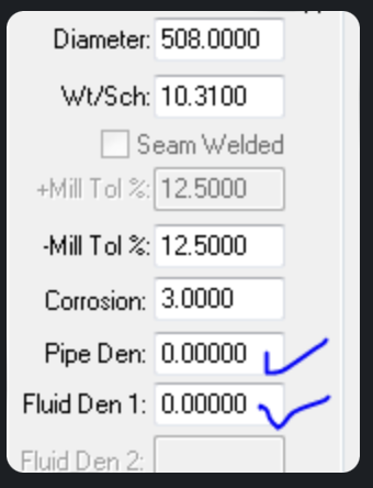
In Peng Method for the buried pipeline analysis the fluid density and the pipe density is used in order to calculate the soil restraint stiffnesses. Afterwards these parameters (pipe density & fluid density) are revised as 0.
If the stress engineer enters the value of seismic effects as gravitational acceleration , no change in the loads will be seen. Since the calculation program has already revised this values as 0 and include them in the value of soil representing restraints. Stress engineer shall enter these seismic forces as F/ L in order to analyze the effects of the seismic loads.

Stress engineers shall enter these seismic forces as F/ L in order to analyze the effects of the seismic loads.
THRUST FORCES
Thrust force is another important point for the buried pipelines stress analysis.
The stress engineer shall stick to the following point for the sake of the analysis.
* The pressure thrust is already accompanied by the code and evaluated under the stress values of hoop stress and axial stress. There is no need to manually calculate the thrust forces due to pressure and import them to the stress analysis input.
* Thrust force due to the change in momentum (flow velocity ) may be calculated manually and imported to the stress analysis input manually. These forces are very low and are not the governing forces.
The thrust force can be calculated by the formula shown in the below figure.


For reference stress engineer can use the following link to prove their calculaion.
For the thrust forces on buried pipelines, the stress engineer should also read and understand the following article for reference. It explains the necessity of thrust restraints and the basic approach. Thanks to David Kent for the simple and certain explanation of the phenomenon.
REFERENCES
ASME B31.3, ASME Code for Process Piping, An American National Standard, ASME, New York.
ASME B31.1, ASME Code for Power Piping, An American National Standard, ASME, New York.
ASME B31.4, ASME Code for Pipeline Transportation Systems for Liquids and Slurries, ASME, New York.
Peng, L. C., 1978, “Stress Analysis Methods for Underground Pipe Lines,” Part 1, Basic calculations, Pipe Line Industry, April, 1978; Part 2, Soil-pipe interaction, Pipe Line Industry, May, 1978.
Peng, L. C., 2009, Pipe Stress Engineering, Liang-Chuan (L.C.) Peng and Tsen-Loong (Alvin) Peng, ASME Pres, 2009.
WhatisPiping.com, 2018, Restrained and Unrestrained Zones in the Buried Pipelines, 17 Oct, 2018, [http://www.whatispiping.com/restrained-and-unrestrained1]
WhatisPiping.com, 2018, Restrained and Unrestrained Zones in the Buried Pipelines, 17 Oct, 2018, [http://www.whatispiping.com/restrained-and-unrestrained2]
WhatisPiping.com, 2018, Few Important points for Stress Analysis based on ASME B 31.4, 17 Oct, 2018, [http://www.whatispiping.com/stress-analysis-based-on-asme-b-31-4]
daviddkent.wordpress.com 2018, Thrust Restraints, 17 Oct, 2018, [https://daviddkent.wordpress.com/2013/01/22/thrust-restraint/