
Centrifugal Pump Piping Design and Stress Analysis
Piping Design Process
The initial piping design for the centrifugal pump starts with preliminary information about the pump. The equipment engineer provides the information for the plant designer. Generally, the provided pump data does not change if the selection has been done correctly.
Piping design starts after the equipment details are provided by a vendor. The type of the pump usually does not change if the data is finalized. However, the dimensions of the base plate and nozzle may change slightly.
Nozzle Loads
The allowable nozzle loads in Table 4 of API 610 are the maximum amount of stress that the piping configuration can impose on the pump suction or discharge.
In case the loads are bigger than the figures in Table 4, the steps in Appendix F must be followed. You can watch the previous video about the pump nozzle loads.
Before piping fabrication isometrics are issued formally, the piping stress engineer is responsible for finalizing the necessary calculations to prevent rework.

Location of Centrifugal Pump
The crucial role of a piping designer is to minimize the length of the suction line of a pump. But while doing this, piping flexibility requirements must be satisfied.
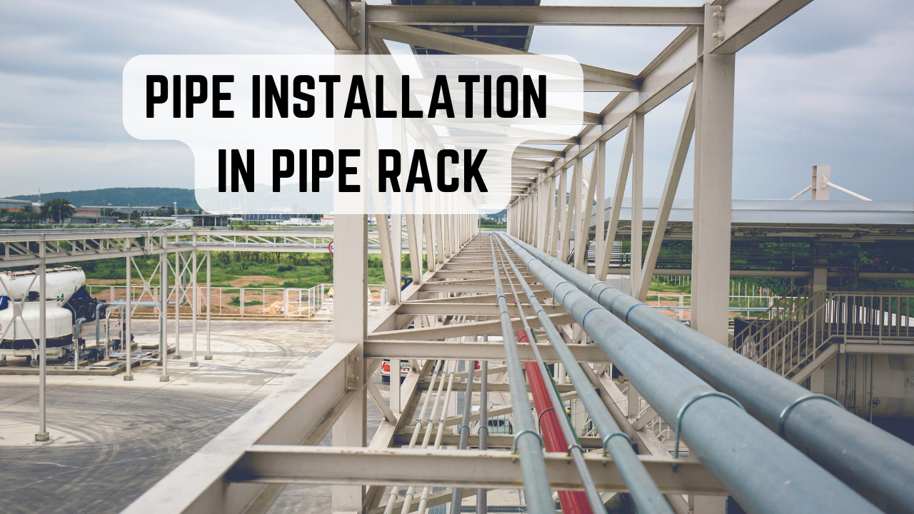
Under the pipe rack is one of the most preferred locations for the pump. It is because of the easy-to-support by pipe rack main beams and/or columns.

The most effective locations would be under the pipe rack if there is no concern about a potential hydrocarbon leakage from the air cooler located over the pipe rack.
Locating the pumps partially outside the rack is also a good solution in terms of the discharge line that can enter inside the pipe rack after a vertical run.


Locating the pumps outside the rack is the most commonly used arrangement in case of potential hydrocarbon spills.
The position of the pump skid depends on where the suction nozzle is feeding from. The suction line should be as short as possible and also as close as possible to the source to achieve minimum pressure loss. So, the pump side on the skid should be close to the source rather than the motor side.

Piping Stress Analysis For Centrifugal Pump
This is a typical and most common pump discharge arrangement application.

As the allowable nozzle loads are low, this type of arrangement must be carefully supported.

In this example, the discharge line is designed vertically. The line is to be supported as close as possible to the elbow to reduce the weight impact of the valves on the pump’s discharge nozzle. But, as the pump’s expansion is vertically upward, the pump and the hanger support will interact with each other. In this design, the hanger support designed according to tensile force operates contrary to the intended purpose of the design, which is an undesirable situation. This is why, a spring support should be used. This will carry the line even if the vertical expansion occurs and so, protect the nozzle from overload.
Also “bellow” can be used within the design both for suction and discharge.
But this type of design can be applied if you have limited space and or at low operating temperatures.
At elevated temperatures, the weight of the valves and all piping will have to be carried by the nozzle due to thermal expansion. In addition to vertical support, horizontal restraints will need to be added to manage the expansion and external forces. So, we should improve our piping design to protect the pump nozzle.


A useful book by PENG for Piping Stress Engineers
Pump Discharge Nozzle Alternative Piping Design
In the oil and gas industries and also the petrochemical industry, another design method is being applied for the pumps that are being operated especially at elevated temperatures.
The applied design is suitable for our motto, “Liken your piping design with equipment behavior.”
“Liken your piping design with equipment behavior”
Let’s look at the design in detail;
First, we should see the discharge nozzle from the suction side. The discharge nozzle expands in the vertical direction, which is why we should escape from it by an elbow. Then, the pipe routing continues downward for better support. Following this, the valve and check valve can be located horizontally.

As you can see, vertical expansions of the pipe and the pump are now similar.
While looking from the plan, a pipe stopper in this direction has been assigned, aligning to the pump’s centerline. This will restrain thermal expansion and so, prevent overload on the pump discharge nozzle.

Pump Suction Nozzle Piping Design
The suction line must be as short and as close as possible to the source. A piping stress engineer should carefully design the suction piping together with a piping designer.
Once we look at the suction nozzle’s thermal expansion, we can see that it is in the shaft direction. Any long-run piping will interact with the suction nozzle and so pump. So, we should route the suction line as short as possible in the shaft direction. A vertical or horizontal turn will help the suction line’s expansion. Hence, the suction nozzle expansion will be smoother.
In some circumstances, a Teflon plate can also be used for the first support after the nozzle, which will reduce the friction force in the nozzle direction, reducing the nozzle load.

When you check these two designs, the valve design lowered to ground level is more manageable and cost-effective in terms of piping stress engineering compared to the design stacked on the pump nozzle. Because there will be no structure requirement and no supporting device is required like the spring hanger. All of these items impact the cost.
The disadvantages are insufficient space for maintenance and drain requirements between the valves due to pocket.


Non-Destructive Examination (NDE) plays a crucial role in ensuring the integrity of welded pipe joints. The selection of NDE methods depends on material type, pipe thickness, and applicable American codes such as ASME B31.3, ASME Section V, and API 1104.