

Re-boiler Piping Stress Analysis
Designing the piping system between a heat exchanger and a pressure vessel is a task of significant impact, involving careful consideration of thermal expansion, support placement, stress intensification, nozzle loads, and fatigue. By following best practices in piping stress engineering, engineers can ensure the system's integrity, safety, and reliability. Your proper analysis and strategic design choices carry a significant weight in achieving a robust piping system capable of withstanding the demanding conditions of industrial operations.
We have modeled that demonstrates the piping connection between a heat exchanger and an elevated pressure vessel (column). This practical tool provides a clear visual representation of an actual application in a plant, making it easier for you to understand the complex system.

The heat exchanger’s TEMA type is BHU. It is a re-boiler. Because of the process requirements, it is on an elevated concrete saddle.
The fixed saddle is located close to the pipe rack. This means the piping design should be likened to the exchanger’s behavior.

Vapor Outlet Piping
See the above picture. This is a vapor inlet nozzle that comes from the re-boiler. As you can see, the pipe routing does not go directly downward to the re-boiler. The first reason is the lack of support location. Even if you support the line with a big structure from the ground, piping stress requirements will not match, and the nozzles will be overloaded. This is the second reason why we should avoid this.
So, the designer made a turn and located the first support that carried the line to reduce the stress on the column’s nozzle. The support is a special support attached to the vessel. Its aim is to carry the line and restrain it on horizontal movements.

Special Support
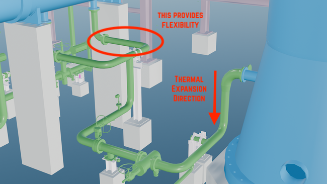
Following that, the line enters the pipe rack structure. As you can see, a stopper is located in this direction, mainly due to thermal expansion. It is desired to be as close as possible to the top nozzles, which is also required for seismic loads. This will reduce the moment on the nozzles due to thermal expansion.

The next line is the condensed outlet line. It comes from the bottom head of the column, so the direction of thermal movement is downward. Because of that, the support is restraining only the horizontal movement. As we explained earlier, the line’s support is far from the vessel to provide flexibility to the piping line.
Following that, the line connects to the re-boiler from the bottom nozzles. The piping flexibility is perfectly considered. As the nozzle’s thermal expansion is downward, the piping line escapes from the exchanger by elbows to provide flexibility.
Condense Inlet Piping
The third line is an outlet line from the tube side. Here, the line is routed vertically until the ground elevation and a small expansion loop are available. There are several reasons for choosing this type of routing. One of them is that vertical thermal expansion is compensated, and the three instrument connections are located over the line. Without the expansion loop, the rigid support and the nozzle contradict each other, causing overstress on the nozzle.
On the horizontal line, the valves are the reason for the many supports. As you can see, the stop and fixed saddle location are the same. This matches our motto, “Liken your piping design with equipment behavior.”

The final line is the tube outlet line, which is identical to the tube inlet line. The vertical line is supported as close as possible to the elbow, and then the valve is supported. A support is used for the valve on the same line as the fixed saddle to match our motto, “Liken your piping design with equipment behavior.”
“Liken your Piping Design With Equipment Behavior”


In conclusion, the detailed design and stress analysis of the four piping lines between the reboiler and pressure vessel illustrates the critical importance of precision and thoroughness in engineering applications. By adhering to industry standards and leveraging advanced analytical tools, we ensure the reliability, safety, and efficiency of our systems. This case study underscores the value of meticulous planning and execution in piping design, highlighting the essential role of engineers in maintaining the integrity and performance of industrial plants. Through continuous learning and application of best practices, we can continue to improve our processes and contribute to the advancement of the field.

This blog is intended as a guide to determining the minimum safe spacing of plants and equipment in Oil Refineries, Petrochemical Complexes, and similar installations.
The spacing recommendations will apply in the absence of Clients' standards or supplement such standards where necessary. They are based on current industry practice.
The spacing recommendations aim to ensure that available plot areas are used economically without affecting personnel safety or plant vulnerability.