Safe Distance During Pneumatic Test
Pneumatic testing is an essential procedure to ensure the integrity of piping systems and pressurized equipment. However, it carries inherent risks due to the high levels of stored energy in compressed gases. For safety, maintaining a safe distance from the test area is crucial to prevent injury in case of a failure. This article outlines the key safety considerations and guidelines for establishing safe distances during pneumatic testing.
What is Pneumatic Testing?
Pneumatic testing involves pressurizing a piping system or pressurized equipment using air or another gas (often nitrogen) to verify the strength and leak tightness of the system. Unlike hydrostatic testing, where water is used as the medium, pneumatic testing involves compressible gases that store significantly more energy. As a result, any failure during a pneumatic test can lead to a sudden and violent release of energy, making safety precautions critical.
Key Hazards in Pneumatic Testing
High Energy Release: Compressed gases store large amounts of energy, and any rupture or failure can cause an explosive release, generating flying debris and high-velocity projectiles.
Noise Hazards: Sudden releases of gas under pressure can create loud sounds that can cause hearing damage.
Pressure Wave: A failure can generate a pressure wave capable of causing structural damage or bodily harm to personnel nearby.
Safe Distance Calculation
To ensure personnel safety during pneumatic testing, industry standards like ASME B31.3 and API 574 recommend guidelines for calculating the minimum safe distance. Several factors influence this distance, including:
Test Pressure: Higher test pressures result in higher stored energy, which increases the safe distance requirement.
Test Volume: The larger the volume of gas under pressure, the greater the risk of failure.
Pipe or Equipment Material: The material’s strength and toughness determine its ability to withstand pressure without failure.
A typical rule of thumb for determining the safe distance is using the following formula:
SAFE DISTANCE FORMULA
Where:
D = Safe distance in meters
E = Stored energy in joules, a function of test pressure, volume, and pipe material properties.
C = Safety constant (typically between 4.5 and 6)
This formula helps approximate the distance where the risk to personnel is minimized.
Formula for Stored Energy (Ideal Gas Law)
For an ideal gas, the stored energy can be approximated by:
Stored Energy in Joules
Where:
E = Stored energy (in joules)
P = Test pressure (absolute pressure, in pascals)
V = Volume of the pressurized system (in cubic meters)
Po = Atmospheric pressure (absolute pressure, in pascals, typically 101,325 Pa)
ln = Natural logarithm
This equation assumes that the gas behaves ideally and takes into account the relationship between pressure and volume in the system.
Steps for Calculation
1.Determine the Test Pressure: The test pressure should be in absolute terms. For example, if the gauge pressure is 10 bar (1,000,000 Pa), then the absolute test pressure P is:
P=1,000,000 Pa+101,325 Pa=1,101,325 Pa
2.Calculate the Volume: The volume of the pipe or vessel can be calculated using the formula for the volume of a cylinder:
Volume of Cylinder
Where:
D = Pipe diameter (in meters)
L = Pipe length (in meters)
For example, if the pipe has a diameter of 500 mm (0.5 meters) and a length of 100 meters:
Volume calculation
3. Perform the Stored Energy Calculation:
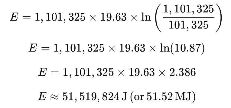
Using the stored energy formula, with the test pressure P=1,101,325 Pa, volume V=19.63 m3V=19.63m3, and atmospheric pressure P0=101,325 PaP0=101,325Pa:
Stored Energy Calculation
Conclusion on Stored Energy
In this example, the stored energy in the system is approximately 51.52 megajoules (MJ). This energy can be released in the event of a failure, which explains why maintaining a safe distance is crucial during pneumatic testing.
Practical Consideration
As seen in this calculation, the amount of stored energy can be significant, especially for large systems under high pressure. To mitigate risk:
Apply safety factors to calculated safe distances.
Ensure that the piping or equipment has been properly inspected before testing.
Conduct the test at a lower pressure if possible and monitor for any signs of failure or leaks.
By following these precautions, along with accurate stored energy calculations, you can ensure the safe execution of pneumatic tests.
Industry Standards and Guidelines
ASME B31.3 – Process Piping Code: Section on pneumatic testing outlines safety procedures and recommends keeping personnel at a minimum distance.
OSHA (Occupational Safety and Health Administration): While OSHA doesn’t provide specific distances, it emphasizes the need for hazard assessment and personal protective equipment (PPE).
API 574 – Inspection Practices for Piping System Components: Provides guidelines on testing procedures and safe distances.
General Safety Measures
Barricading the Test Area: Erect barriers around the testing area to prevent unauthorized personnel from entering.
Monitoring Pressure and Volume: Use reliable instrumentation to monitor pressure and control the amount of gas used in the test. Ensure pressure does not exceed 110% of the design pressure.
Personnel Evacuation: Ensure that all non-essential personnel evacuate to a safe distance prior to pressurizing the system.
Remote Monitoring: Where possible, conduct pressure monitoring and control from a safe, remote location.
Emergency Procedures: Develop and communicate an emergency plan in case of unexpected failures, including evacuation routes and first aid support.
Example: Safe Distance for a Typical Test
Let’s assume a pneumatic test on a piping system with the following parameters:
Test Pressure: 10 bar
Pipe Length: 100 meters
Pipe Diameter: 500 mm
Conclusion
Pneumatic testing is a high-risk procedure due to the energy stored in compressed gases. Following established guidelines for safe distances, along with proper risk assessments, will ensure the safety of personnel. Always adhere to industry standards such as ASME B31.3, API 574, and OSHA, and develop comprehensive safety protocols for your specific test scenario.
It is recommended that the pneumatic testing requirement of a piping system or pressurized equipment be challenged due to the high-risk potential for human damage. This can be done by strengthening the piping system by adding additional supports for hydro testing and taking necessary precautions to test the equipment as well for hydrostatic testing.
By keeping safety a top priority and implementing these precautions, the risks associated with pneumatic testing can be significantly mitigated.


Non-Destructive Examination (NDE) plays a crucial role in ensuring the integrity of welded pipe joints. The selection of NDE methods depends on material type, pipe thickness, and applicable American codes such as ASME B31.3, ASME Section V, and API 1104.