

Piping Stress Analysis of Heat Exchanger
Piping Stress analysis plays a crucial role in shell and tube heat exchangers. Heat exchangers include various temperatures inside so, the expansion behavior varies as well. Engineers must ensure to find the right displacement of the nozzles.
A heat exchanger in general consists of 2 pieces, shell side and tube side. This is why it is called, a ‘shell and tube heat exchanger’.
The average temperatures are different on each side of the exchanger. The piping stress engineer should consider this while calculating the displacement of the nozzles.
There are 4 main nozzles on ‘the shell and tube heat exchanger’. Shell inlet, shell outlet, tube inlet, and tube outlet.
Displacement starts from a fixed saddle. The fixed saddle is located on the far side of the pipe rack which is different from the horizontal vessel.

A Typical Heat Exchanger
The shell side average operating temperature is considered to calculate the shell side nozzle’s displacement.
Due to the different average operating temperatures on each side, the tube nozzles’ thermal displacement is to be considered separately. The shell side and then tube side displacement are to be added to identify the horizontal displacement of the tube side nozzles.
HEAT EXCHANGER TUBE INLET NOZZLE PIPING
This is an ideal pipe design. However, it contains some design errors because it has not been checked by a piping stress engineer.

Heat Exchanger Tube Inlet Nozzle Piping
At first, additional support is required in the highlighted area. Because the deflection will occur in this zone due to the weight of the pipe and the weight of fluid inside the line.

Support Required In Red Highlighted Area
The second issue is the stopper that limits the expansions in this direction is placed on the pipe rack. The distant location of the stopper from the exchanger's tube inlet nozzle will cause excessive moment on the nozzle connection and consequently, excessive stresses in the nozzle connection.
Third and finally, due to the deflection mentioned in the first point, if a support is added as shown in the figure, the pipe will extend vertically upward. Therefore, it will not properly sit on this support. Even if it does, especially at high operating temperatures, there will be vertical loads on the nozzle.
Third and finally, due to the deflection, you can place a rigid support as shown but another issue is the pipe will expand vertically upward. Therefore, the pipe will not properly sit on this support. Even if it does, especially at high operating temperatures, there will be vertical loads on the nozzle.
Therefore, as I have always mentioned, since we cannot make too many changes to the equipment, we should make revisions that will move the pipe in a manner similar to the behavior it exhibits at the operating temperature of the equipment.

WRONG PIPING DESIGN AND SUPPORT LOCATION
“Liken your piping design with equipment behavior”
As can be seen here, the elevation of the pipe has been altered. Additionally, support has been added. If you pay attention, you will notice that the support is positioned at the same level as the fixed saddle. The reason for this, as you can imagine, is to place the stopper at the same level as the fixed saddle. This way, the equipment and the pipe behave in the same manner at operating temperatures.

Proper Piping Design and Supporting
The bottom of the pipe elevation is at the same level as the bottom of the shell elevation of the heat exchanger. Additionally, since the pipe stopper and fixed saddle are positioned at the same level, the pipe and equipment will behave in the same way at the operating temperature. This will minimize stresses on the nozzle and, consequently, protect the equipment and pipe from excessive stresses.
HEAT EXCHANGER SHELL INLET NOZZLE PIPING
One of the nozzles on the heat exchangers is 'Shell Inlet Nozzle.' As seen in this example, the Shell Inlet Nozzle is positioned at the farthest distance from the fixed saddle. Therefore, the thermal expansion of the shell inlet nozzle will be relatively greater than the other nozzles.
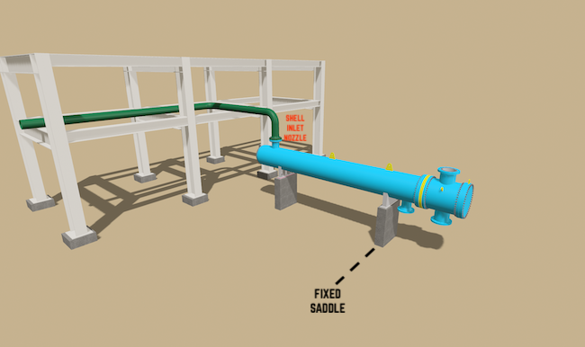
Heat Exchanger Inlet Piping Design Issue
Piping design like this will resist the thermal expansion of the exchanger. Due to its own weight, the pipe will tend to expand towards the exchanger. However, the exchanger will tend to expand in the direction of the pipe rack due to the fixed saddle position.
Ultimately, excessive loads at the connection point, the nozzle, between the pipe and the exchanger will result in high stresses, leading to excessive stress at the Shell connection of the nozzle.
To prevent the occurrence of excessive stress, we will need to make some revisions to the pipe design.
3-dimensional changes in pipe routing will always help the pipe flexibility. So, as seen in the below photo, the revision is to provide a downward turn to the pipe from the nozzle. This downward turn will give additional flexibility to the pipe. At the same time, the pipe will not create resistance against the expansion direction of the exchanger, so there will be no minimum loads.

Proper Piping Design for Heat Exchanger Shell Inlet Nozzle
Here, to achieve a similar behavior between the pipe and the exchanger, you can relocate the trunnion under the elbow to align it with the height of the exchanger's saddle. This way, the axial moment that may occur on the nozzle is minimized.
You can watch the YouTube video related to Heat Exchanger Piping Design, Pipe Supporting and Stress Analysis;
Shell Inlet Piping Stress Analysis and Design of Heat Exchanger
Shell Inlet Piping Stress Analysis and Design of Heat Exchanger