

Storage Tank Piping Stress Analysis
Storage tanks, which come in various sizes, from small to extremely large, are commonly used in industrial settings to store various products.

Storage Tank with Floating Roof
In processing plants such as oil refineries, chemical works, or food processing factories, it is often necessary to pause production at various process stages. This could be to allow reactions to occur at different rates or to bring together products from different intermediate processes for a finishing process. At the end of the production process, the product cannot be immediately delivered to the customer, and a further pause may be necessary to accumulate a suitable batch of material for transport. All of these pauses create a need for bulk storage.
Storage tanks can be constructed above ground, in-ground, or below ground. They come in various shapes, including vertical cylindrical, horizontal cylindrical, sphere, and rectangular.
Different types of products can be stored, such as gases, liquids, solids, and mixtures. Storage tanks for particulate solids are usually called silos. The temperature required for storage varies depending on the product. For instance, high-temperature heated storage tanks are used for products like bitumen. On the other hand, LNG requires a temperature as low as -163°C for storage, while for liquid nitrogen, the temperature should be as low as -196°C.
It's crucial to differentiate between storage tanks and pressure vessels. According to regulatory documents, pressure vessels are those vessels that can withstand a maximum pressure of over 0.5 barg. Therefore, it's convenient to define storage tanks as vessels that can withstand a maximum pressure of less than 0.5 barg.
Tank Nozzle Loads
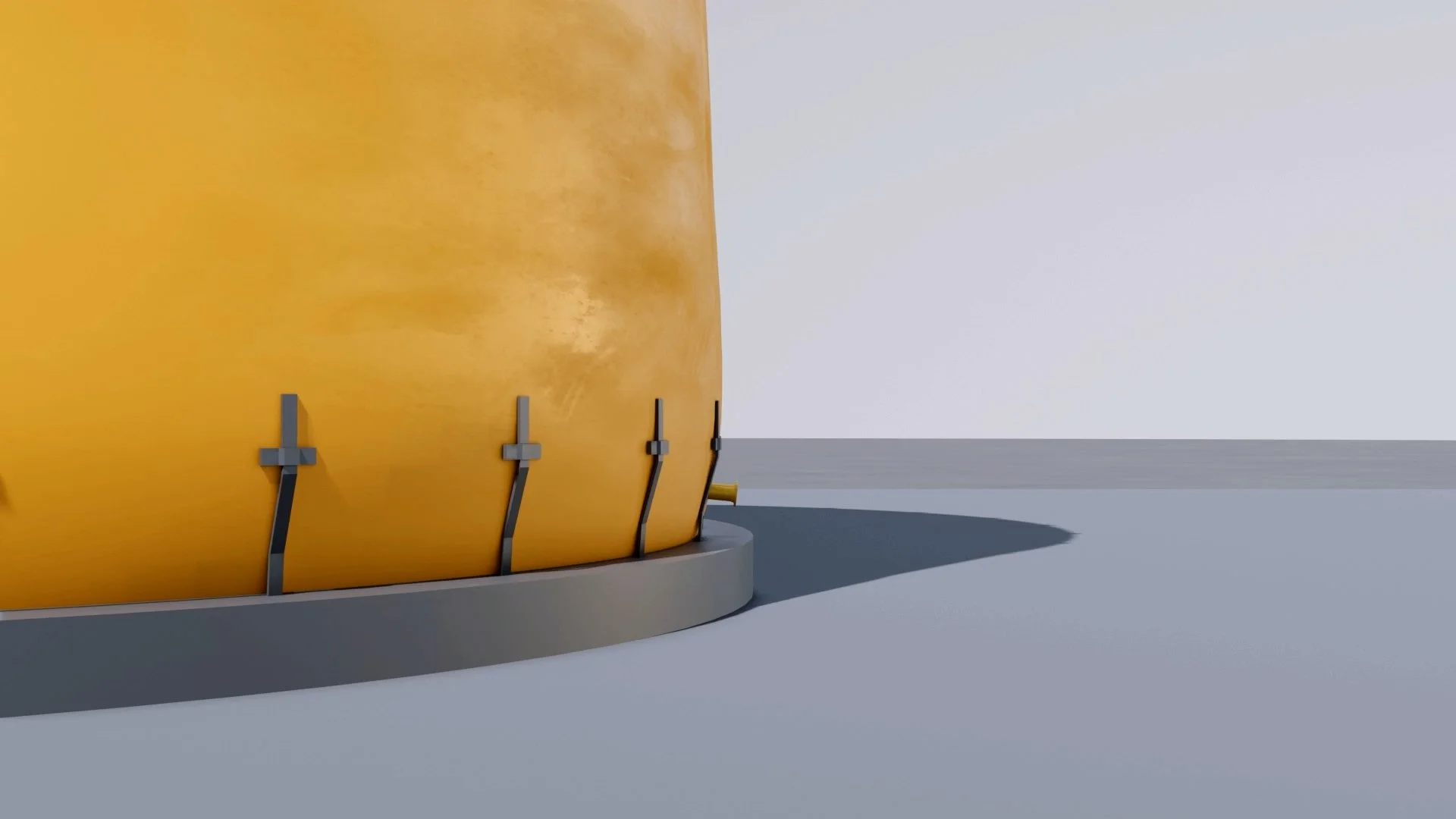
The hydrostatic pressure exerted by a liquid stored in a tank increases linearly with the height of the tank. The maximum pressure is experienced at the bottom of the tank. If the tank's shell is not attached to the bottom plate, the pressure will cause a radial displacement, with the maximum displacement occurring at the bottom. However, since the shell is attached to the bottom plate, the radial displacement of the shell is restricted to zero at the bottom. This explains the shape formed at the tank's bottom connection.
A tank can be considered a vessel, so its connections can be treated in the same manner as vessel connections. However, the tank connections located at the very bottom of the tank cannot be treated like ordinary vessel connections due to some unique characteristics associated with that region.
Connections of this type create significant rotations in the connecting piping due to the bulging of the tank shell under the product head and the hydrostatic pressure of the liquid contained. The surroundings of the connection are also much more complex than vessel connections. Therefore, the flexibility of these low-type tank connections cannot be readily estimated using vessel connection formulas. A set of unique approaches is necessary to handle the interaction between the tank and the piping.
Shell Nozzle Rotation @ Tank Fully Filled
Billimoria and Hagstrom have developed a set of stiffness coefficients and allowable load factors for analyzing low-type tank connections. They used information generated by their proprietary computer program and their company's experiences. Later, Billimoria and Tam field-verified these data and formulas, which were then adopted by API Standard 650. These formulas and data are used to design steel storage tanks. The "Appendix P - Allowable External Loads on Tank Shell Openings" of API-650 puts this evaluation approach into practice.
The following discussions are based on the approach presented by Billimoria and Hagstrom. As the data involves interpolation between widely separated benchmark values, the results obtained for each specific connection parameter are not very precise. Therefore, allowing for a higher margin on the allowable values is necessary. It is also important to note that API Standard 650 does not require this approach. Its use is left to the agreement between the manufacturer and the purchaser.

Standard API 650 also states: “It is not intended that this appendix (evaluation method) necessarily be applied to piping connections similar in size and configuration to those on tanks of similar size and thickness for which satisfactory service experience is available.” Therefore, the piping engineers may or may not use the exact approach outlined here. However, the phenomena here are significant and should be dealt with properly. In particular, the displacement and rotation of the tank shell have created some known problems and should be handled with care.
Designing an external piping system to connect to a large cylindrical storage tank with a thin wall can be challenging. The piping designer must take into account the stiffness of the tank shell, the radial deflection, and the meridional rotation of the shell opening at the opening-shell connection caused by product head, pressure, and temperature differences. To ensure the safety of the tank, the piping designer and the tank designer must coordinate their work to ensure that the piping loads imposed on the shell opening by the connected piping are within safe limits. Although three primary forces and three primary moments can be applied to the mid-surface of the shell at an opening connection, only one force (FR) and two moments (ML and MC) are normally considered significant causes of shell deformation.

Primary Loads and Moments on Low-Type Nozzles (API 650)

Storage Tank Behaviour and Piping Stress Analysis
After filling the storage tanks with a process fluid, the bottom shell tends to bend outwards due to the internal hydrostatic pressure. This bending affects the low-type nozzle’s direction. The nozzle may turn downward or upward. Above mentioned approach analysis this low-type nozzle turns under operation conditions as well.
The area where the storage tanks are located is exposed to excessive loads. This is why over time, the tank settles into the ground.
During the hydro test operation, one-third of the settlement occurs while the rest happens throughout the tank's lifespan. Due to this, the piping connections must be removed during the storage tank hydro-test operation. Also, the piping flexibility must be analyzed against the settlement that occurs throughout the tank’s lifespan. This can be done by using rigid support that is properly located after the tank nozzle. Especially the small bore pipes.
For large bore pipes, spring support should be used after the piping stress analysis is done. The spring support will help to eliminate overstress because of the nozzle turn and the tank settlement.

Storage Tank Piping Connection Supported by Spring Hanger
While looking at the plan, a long pipe routing from the tank must be avoided due to the friction forces that will resist the pipe expansion. This will increase axial force against the storage tank. The connected piping must be turned perpendicularly from the tank nozzle direction as short as possible.

Storage Tank Piping (not preferred)

Storage Tank Piping (preferred)
Source: Pipe Stress Engineering (PENG)
This blog is intended as a guide to determining the minimum safe spacing of plants and equipment in Oil Refineries, Petrochemical Complexes, and similar installations.
The spacing recommendations will apply in the absence of Clients' standards or supplement such standards where necessary. They are based on current industry practice.
The spacing recommendations aim to ensure that available plot areas are used economically without affecting personnel safety or plant vulnerability.