

Expansion Loop Design and Calculation Details
We'll discuss the technical details of this important component and empower engineers with the knowledge to design effective expansion loops. We'll provide expert tips and tricks based on industry experience to optimize the performance of expansion loops. Join us as we explore the expansion loops and enhance your understanding of piping systems.
It is important to perform a flexibility check on the lines situated on long pipe racks, especially for pipes that transport fluids with high temperatures. These lines tend to cause excessive expansion at the end of the pipe racks. To prevent or control this expansion, a line stop is essential at the center of the line or the native zero point of the line where the expansion is zero.

Line Stops on a Pipe Rack
To prevent or control this expansion, a line stop is essential at the center of the line or the native zero point of the line
After that, you need to inspect the expansion distance at the end of the pipe racks. If the expansion at the far end of the pipe rack is enough to handle, the length of the pipe shoe should be kept longer to accommodate thermal expansion growth. However, if the expansion is too long, you should consider a design that includes an expansion loop.

PIPE SHOE LENGHT
Length of the pipe shoes should be kept longer for the line at elevated temperatures if there is no expansion loop considered for the piping line.
Also, it's important to take into account the flexibility of the branch connections, especially at the far end of the racks. If the main line's expansion is high, you may need to reconsider the branch connection design to make it more flexible or install an expansion loop. If you have multiple branch connections, this could end up being quite costly for you. It is preferable to use an expansion loop on the main line instead.

BRANCH CONNECTION AT THE END OF THE RACK
Flexible connection may required at the end of the rack if the main line expansion is excessive.
In some cases, you can consider using an expansion loop to account for occasional forces, especially seismic loads. In case the seismic loads on the stopper support are high, we can divide the load by using an expansion loop on the rack.
When designing an expansion loop, consider all the lines that require an expansion loop should be located close to each other. The largest expansion loop must be located outside the other loops with less growth.
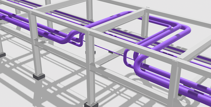
EXPANSION LOOP
When designing an expansion loop, consider all the lines that require an expansion loop should be located close to each other. The largest expansion loop must be located outside the other loops with less growth.
Expansion Loop Calculation
You can see below how this formula was derived and the purpose of the coefficients used in the formula.


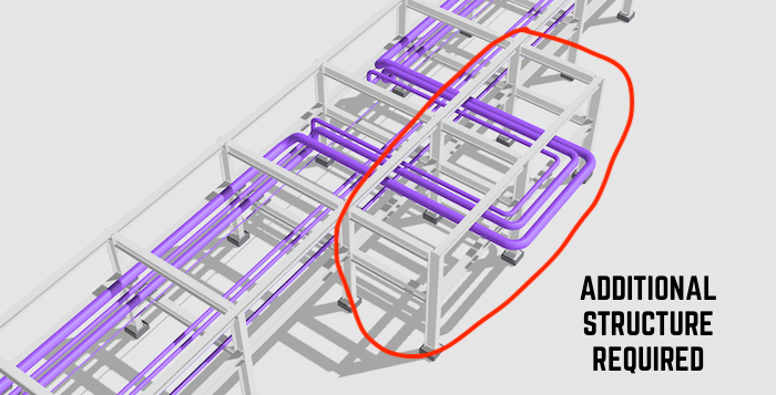
LONG EXPANSION LOOP
The height of the expansion loop should be a close to the pipe rack with. Otherwise additional structure may required that will impact the project cost.
We should add one more expansion loop to reduce the height of the loop. This means that the length will be reduced to half.
Expansion Loop Design and Hand Calculation

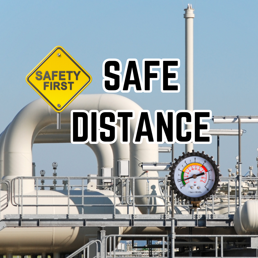
This blog is intended as a guide to determining the minimum safe spacing of plants and equipment in Oil Refineries, Petrochemical Complexes, and similar installations.
The spacing recommendations will apply in the absence of Clients' standards or supplement such standards where necessary. They are based on current industry practice.
The spacing recommendations aim to ensure that available plot areas are used economically without affecting personnel safety or plant vulnerability.