

Comprehensive Guide to Piping Isometric Drawings
Piping isometric drawings are technical drawings used in the piping design industry which consist of three-dimensional indications of piping systems which should have detailed information for the construction, mechanical completions, maintenance, and operation aspects of piping systems in projects within such industries as oil and gas, chemical, pharmacy, power, and water treatment based on project requirements such as P&ID and project specifications.

Piping Isometric Sample-1
These drawings play a pivotal role in the project, from the fabrication phase to the installation phase, providing crucial guidance for the construction department. But their impact continues. After the construction and installation phases, the mechanical completion and operation teams can also benefit from these drawings. They serve as a common language, facilitating communication and understanding among different teams, making each member feel integral to the project.
Piping isometric is like a 3D view of a piping system on a 2D sheet with an isometric view drawn at a 30-degree angle from a horizontal plate to imitate a three-dimensional view without a scale by showing how pipes, fittings, valves, and all other components are positioned project different from the regular 2D drawings, isometrics offer fairer information for those who will utilize these drawings.

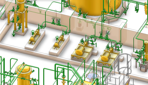
Piping Isometric Sample-2
Isometric drawings should include detailed notations such as pipe sizes, dimensions, coordinates, lengths, directions of pipe runs, materials, specifications for each component, and continuation details. They should also indicate the orientation and location of fittings, valves, flanges, instruments, and all other elements.
All components' necessary dimensions should be meticulously provided for the utmost precision and accuracy. Actual project coordinates, including continuation details, should be clearly indicated on the isometric and elevation details on some turning points. This level of detail ensures that the construction department can understand and carry out all fabrication activities with absolute accuracy, providing a sense of reassurance in the reliability of these drawings.
Symbols dedicated to all components, such as fittings, valves, pipes, and instruments, should be represented based on international industry standards. Submitting project isometric legends within project documentation for context and common project awareness for all involved personnel is better.
MTO (Material Take Off) should be at present on piping isometric where isometric is produced for fabrication purposes. On this point, MTO should include all components represented on the isometric unless otherwise indicated, such as in tie-in isometrics or continuation isometric with the necessary information such as part numbers, sizes, quantities, descriptions, item codes (if the project has unique item coding system for each unique item) specifications.
These drawings were only hand-drawn back in time, but hand-drawn piping isometrics are less common nowadays. Hand drawings are like sketches, which are most likely to describe situations where computer-aided design programs would consume more time to deliver the outcome, which is also very rare but still in use.

Currently, a specific range of software, such as AVEVA E3D, AVEVA PDMS, AutoCAD, Smart Plant, and other CAD software, is in place to reduce project costs based on the manhours required to produce piping isometric drawings by modeling the piping system into a model of the actual project and automating man-related errors’ direct and indirect costs.

Also, modeling the project with 3D computer-aided software reduces the risk of clashes which can easily happen in large projects, change management systems can be built on 3D systems, revisions can be carried out easier than on 2D systems, and these models can be turned into digital twin of the actual facility for further instances which will give outstanding benefits to operators. The actual and whole list of benefits of the 3D models can be another subject to another topic.

Reciprocating compressor piping systems are highly sensitive to pulsation and vibration effects caused by dynamic pressure fluctuations. If these effects are not properly considered during the design stage, they may lead to excessive vibration, fatigue damage at branch connections, and even premature failure of piping components. For this reason, an analogical (acoustic and pulsation) study plays a critical role in evaluating the dynamic behavior of compressor piping systems.