

Right-Hand Rule
The Right-Hand Rule is a concept used in various engineering and physics fields, including piping stress analysis, to determine the direction of moments and forces, particularly in 3D coordinate systems. In piping stress calculations, it helps in understanding how moments and torques act on pipe systems when subjected to different loads, such as thermal expansion, pressure, or external forces.
Here's how the Right-Hand Rule is applied:
For Moments:
Step 1: Curl the fingers of your right hand in the direction of rotation or the moment (torque).
Step 2: Extend your thumb straight out. The direction of your thumb indicates the direction of the moment vector.
For example, if a pipe is experiencing a bending moment that causes it to rotate in a clockwise direction (when viewed from a particular side), curling your fingers in that direction will point your thumb towards the axis or direction of the moment.
For Coordinate Axes:
When dealing with the global coordinate system (X, Y, Z) in 3D stress analysis, the Right-Hand Rule is often used to orient the coordinate axes:
Thumb = X-axis (positive direction)
Index Finger = Y-axis (positive direction)
Middle Finger (perpendicular to the plane of X and Y) = Z-axis (positive direction)

Right-Hand Rule
Showing the Axes
Application in Piping Stress Analysis:
Moments due to Thermal Expansion: When pipes expand due to temperature changes, the Right-Hand Rule helps you determine how the bending moments affect different sections of the piping.
Pipe Support Reactions: The rule helps in visualizing the reaction forces and moments on supports and restraints.
Torsional Moments: When torsional moments are introduced in a pipe (e.g., due to twisting), the Right-Hand Rule helps determine the direction of the moment vector, which is critical for accurate stress calculations.
In software tools like CAESAR II, which are commonly used for piping stress analysis, the Right-Hand Rule is often implicitly applied to ensure that the moments and forces are correctly interpreted in the system's coordinate axes.

An up-to-date and practical reference book on piping engineering and stress analysis, this book emphasizes three main concepts: using engineering common sense to foresee a potential piping stress problem, performing the stress analysis to confirm the problem, and lastly, optimizing the design to solve the problem.
Nozzle Moment Direction
In piping stress analysis, understanding the nozzle moment direction is crucial for evaluating the loads on equipment nozzles (e.g., pumps, compressors, pressure vessels). The Right-Hand Rule helps determine the direction of moments acting on the nozzle due to external forces, such as thermal expansion or internal pressure in the piping system.
Steps to Identify Nozzle Moment Direction Using the Right-Hand Rule:
Identify the Axis of Rotation:
Nozzles typically connect piping systems to equipment, and moments can act around the three main coordinate axes: X, Y, and Z (or radial, axial, and tangential directions depending on the coordinate system in use).
Moments at the nozzle are generated due to forces causing the pipe to bend or twist around these axes.
Apply the Right-Hand Rule:
Imagine the moment acting on the nozzle, which can cause the connected pipe to rotate about an axis (X, Y, or Z).
Curl your fingers of the right hand in the direction of this rotation.
Extend your thumb straight, perpendicular to your curled fingers. The direction in which your thumb points gives the moment vector direction.
Example:
If a pipe connected to a nozzle is bending in such a way that the pipe is rotating clockwise around the X-axis (when viewed from a fixed point), the Right-Hand Rule helps identify the direction of the moment. Curl your fingers in the clockwise direction around the X-axis. Your thumb will point in the negative X-direction. This means the moment acting on the nozzle has a negative X-direction.
Conversely, if the rotation is counterclockwise, the thumb will point in the positive X-direction, indicating a positive moment.

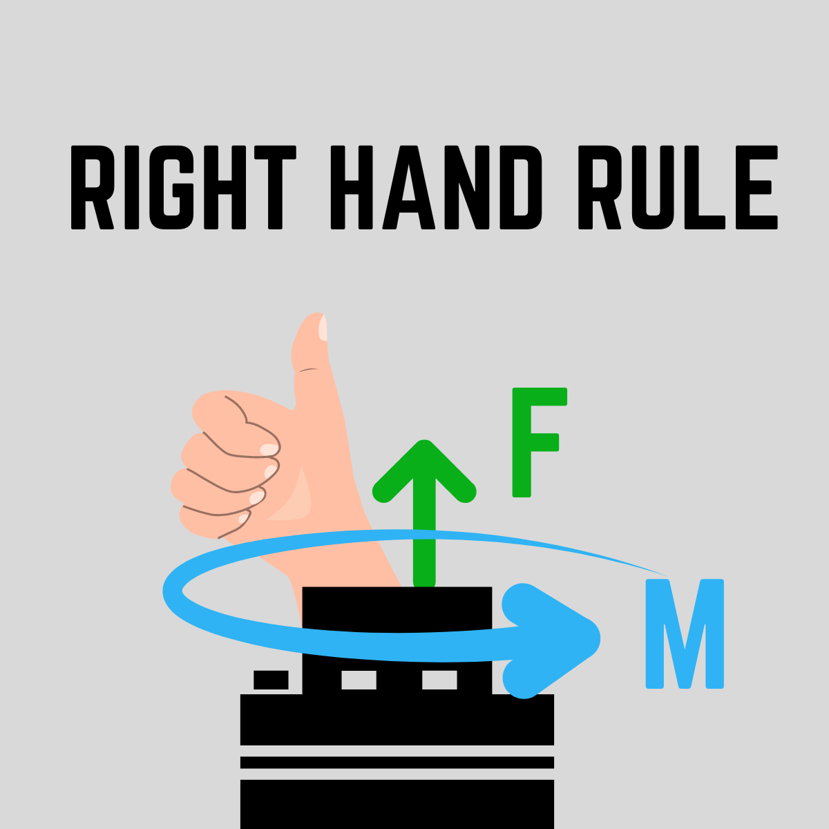
Right-Hand Rule
Showing the Moment and Vector
Nozzle Moment Components:
Nozzle moments typically have three components, and the Right-Hand Rule helps visualize the direction for each:
M_x: Moment around the X-axis (horizontal axis).
Rotation in the X-axis can cause bending moments in the pipe parallel to the ground.
M_y: Moment around the Y-axis (vertical axis).
M_z: Moment around the Z-axis (perpendicular to the X-Y plane).
This is often a torsional moment that results in the twisting of the pipe around the nozzle.
Practical Use in Piping Stress Analysis:
When analyzing nozzle loads in tools like CAESAR II, moments acting on nozzles are often reported in terms of X, Y, and Z coordinates. The Right-Hand Rule ensures that you correctly interpret these moments by associating the reported numbers (positive or negative) with their correct directions:
Positive or negative moments indicate the rotational direction around the respective axis, determined using the Right-Hand Rule.
This information is critical when comparing the calculated moments against nozzle load limits provided by equipment vendors (e.g., following API 610 for pumps or WRC 107/297 for pressure vessels).
By consistently applying the Right-Hand Rule, you can confidently interpret whether a moment is trying to bend the nozzle upward, downward, or twist it in a specific direction. This clarity ensures that the design of piping systems stays within the allowable nozzle load limits, protecting both the piping and the connected equipment.


Non-Destructive Examination (NDE) plays a crucial role in ensuring the integrity of welded pipe joints. The selection of NDE methods depends on material type, pipe thickness, and applicable American codes such as ASME B31.3, ASME Section V, and API 1104.